Home > Miata Tech > Third Generation (NC) Tech > NC Lumbar Installation
How To Install the Rostra Precision Universal Lumbar Kit
Submitted by Dale Disharoon
2008 MX-5 NC GT PRHT w/Leater Seats - Installation of Aftermarket Universal Lumbar Support System Kit
This is my first Miata (thank you Uncle Larry!) and like most of you I'am a Miata car enthusiast, and not a professional car mechanic. To all who are willing to take on this project and follow these instructional steps are solely responsible for their own work. I make absolutely no expressed or implied warranties or guaranties, or take responsibility for any unforeseen outcomes or liabilities while you performed these installations.
Now with that said we, my wife and I, believe at the conclusion of these installations you and your passenger will enjoy the added comfort afforded by this particular aftermarket product. This lumbar support kit should fit all MX-5 NC model years (all having similar seats thus far?) and makes available what we believe should have been originally offered by Mazda. If not included as standard equipment in the original purchase price, at least made available as a popular option on all Miata’s. Hopefully Mazda corporate will include in future Miata’s, like it has in the past, many of the ideas and suggestions like this one coming from their nearly 1-million strong past and present Miata owners and enthusiasts.
Universal Lumbar Kit ordering information: This kit is made by:
Rostra Precision Controls, Inc.
2519 Dana Drive
Laurinburg, NC 28352
P: (910) 276-4853
They DO NOT sell direct to retail customers and I was provided the following distributor information:
Brandon Distributing, Inc.
18629 Simonet Drive
Elk River, MN 55330
P: (763) 241-4172
Email: Joe Brandon
Direct Weblink for product
I purchased two kits, on two separates dates, online from Brandon Distributing Inc., for $81.84/each + shipping via UPS ground (no tax for California delivery!) for a total of $93.41/each.
Item number: 2501453
Item Name: Lumbar Rear Mount Standard Bladder
Item Description: LUMBAR KIT REAR MOUNT (WHEN UPHOLSTERY GLUED TO FOAM)
*NOTE It is important that you order this particular item as it is specifically designed to be placed behind the foam seat padding and, if equipped, the seat heater element. This installation DOES NOT interfere with or diminish the heated seat functions as it’s mounted behind the seat’s heating elements!
I will grade this installation a solid 3, on a scale of 1 to 4, with 1 = easy & 4 = difficult. The second seat installation always goes faster and easier than the first as did our passenger’s seat. My Uncle’s, yes I assisted him with his 2008 MX-5 NC GT PRHT w/leather seats driver’s side install, was even easier and quicker than mine. As for time of installation, I would suggest a full afternoon for each seat. I took my time while photo documenting this installation and hopefully making it easier for you. I cannot overstress carefully reading and familiarizing yourself with all the supplied instructions, parts, and the photos and installation steps I’ve provided. I’m confident that if YOU TAKE YOUR TIME and prepare yourself you too will have a successful outcome from this installation. Remember – HAVE FUN! Dale Disharoon
What's in the box (Figure A)? Carefully read supplied instructions and familiarize yourself with all components before stating! Setup a comfortable, protected/padded floor work area for seats outside the car! Lower car top. *NOTE - More cable ties will be needed for this installation than supplied!
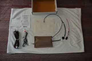 Figure A Figure A
Installation Steps - Paired with Accompaning Photos
- Safety First! Disconnect battery! Installation steps involve connecting supplied wiring components to both the installed lumbar support system and interior fuse box.
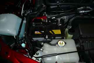 Figure 1 Figure 1
- Carefully remove door sill plate. Remove seat belt strap from strap guide located on upper left of seat (as seated).
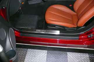 Figure 2 Figure 2
- Figure 3 shows the door sill plate attachment points.
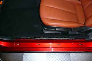 Figure 3 Figure 3
- Locate interior fuse box access door. Remove interior fuse box access door.
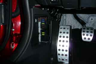 Figure 4 Figure 4
- This is a reference view of the wiring harness that’s located under the door sill plate and leading to the interior fuse box panel.
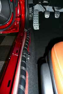 Figure 5 Figure 5
- Loosen and remove the two front driver seat floorboard bolts. This will take muscle and remember to protect your knuckles.
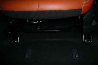 Figure 6 Figure 6
- Loosen and remove the two rear driver seat floorboard bolts. This will take muscle and remember to protect your knuckles!
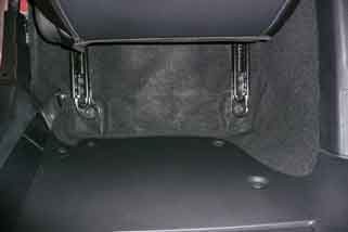 Figure 7 Figure 7
- Tilt the seat back, and using a thin flathead screwdriver gently release the white electrical junction box from the metal support arm. *NOTE - DO NOT ATTEMPT removing the hex-bolt holding the metal arm that supports the white electrical junction as it's welded to the seat frame! Knuckles!
 Figure 8 Figure 8
- Before removing the white electrical junction box plugs, ID each for easy reinstallation! Using a thin flathead screwdriver, gently remove each ID'ed plug (plastic tabs securing each plug easily break-off!). Carefully remove seat up and out of the car’s cockpit area and to your protected/padded work area.
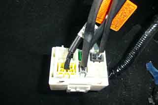 Figure 9 Figure 9
- View showing 4 plugs removed from white electrical junction box.
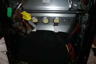 Figure 10 Figure 10
- Place white electrical junction box onto carpeted floorboard.
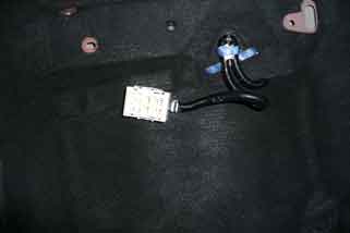 Figure 11 Figure 11
- Layout and size supplied lumbar air pump wiring harness that will connect to the air pump unit located under the front of the driver's seat. DO THIS PRIOR TO CUTTING OR TRIMMING ANY OF THESE WIRES!
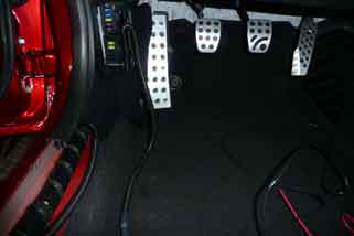 Figure 12 Figure 12
- Cont'd layout and sizing of supplied wiring harness. *NOTE - Use existing wire harness holder under door sill plate to secure supplied wiring harness!
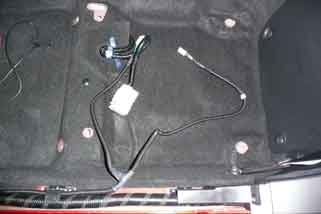 Figure 13 Figure 13
- Close-up of figure13 - Continued layout and sizing of supplied wiring harness. *NOTE - Use existing wire harness holder under door sill plate to secure supplied wiring harness!
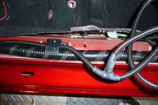 Figure 14 Figure 14
- Cont'd layout and sizing of supplied wiring harness. *NOTE - Run supplied wiring harness under carpet and towards driver's seat and white electrical junction box on floorboard.
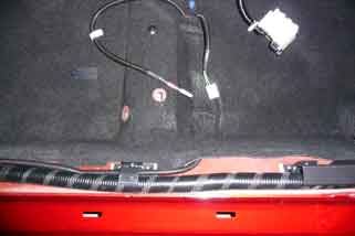 Figure 15 Figure 15
- Finish running supplied wiring harness under carpet, no carpet cutting required! Re-tuck and flatten-out carpet back into place.
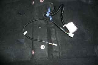 Figure 16 Figure 16
- Remove kick panel and access fuse box. Locate panel ground wire behind tape; connect supplied 5-amp fuse holder hot-lead to 15-amp fuse socket - review step 18.
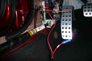 Figure 17 Figure 17
- *NOTE - Connection of supplied 5-amp fuse holder hot-lead to 15-amp fuse socket on panel. The 15-amp fuse has been removed to securely connect the hot-lead wire (shown), and will be reinstalled at the end of these installations.
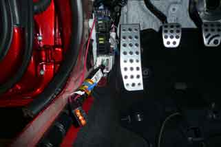 Figure 18 Figure 18
- Cont'd connecting supplied 5-amp fuse holder. Add connector to ground wire. Trim supplied harness wires to fit leaving some slack to tuck into fuse box area.
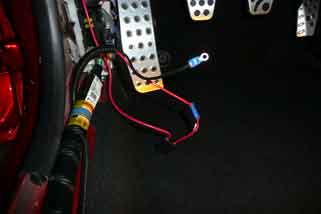 Figure 19 Figure 19
- "Gang" connect common ground wires from supplied harness and fuse box panel.
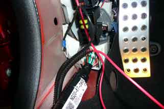 Figure 20 Figure 20
- Secure wire slack and check all connections.
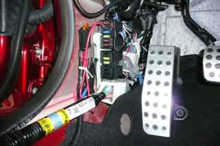 Figure 21 Figure 21
- Replace kick panel. *NOTE - Easy access to supplied 5-amp fuse holder. Replace fuse box access door.
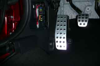 figure 22 figure 22
- Rocker switch plate installation. For clean install of rocker switch plate - TAKE YOUR TIME! Make a couple of spare back-up copies of this supplied instructional page.
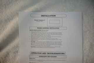 Figure 23 Figure 23
- Position the rocker switch for easy and unobstructed access. Recommend placement as pictured - left front of seat area (as seated) on hard plastic seat molding piece.
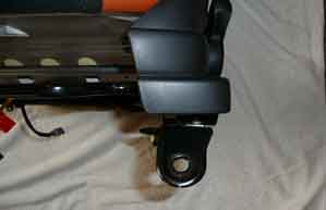 Figure 24 Figure 24
- Cut-out and, while using a piece of transparent adhesive tape, center and secure the rocker switch template.
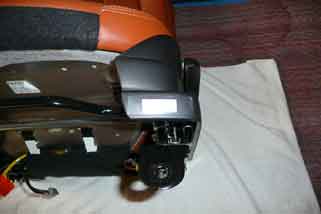 Figure 25 Figure 25
- Close-up of step 25.
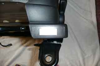 Figure 26 Figure 26
- With a new sharp razor blade cut along template outline. TAKE YOUR TIME and don't overcut!
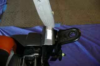 Figure 27 Figure 27
- Remove all uncut plastic pieces around entire cut-out area.
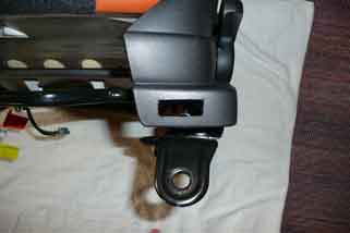 Figure 28 Figure 28
- Size supplied rocker switch-wiring harness. If required, trim newly cut opening for a close, tight fit. At this point be careful not to “snap and lock” rocker switch-wiring harness into place.
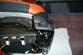 Figure 29 Figure 29
- Lay rocker switch holding plate onto supplied foam backing piece. Press firmly making sure rocker switch locking tabs, on backside, pushes thru foam.
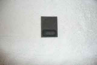 Figure 30 Figure 30
- Carefully cut-out foam backing.
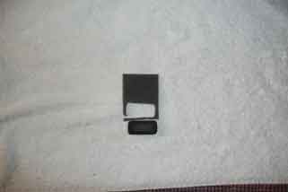 Figure 31 Figure 31
- Cont'd cutting out of foam backing.
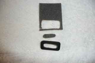 Figure 32 Figure 32
- Turn over and make sure rocker switch locking tabs have punched all the way thru foam and self-adhesive protective layers.
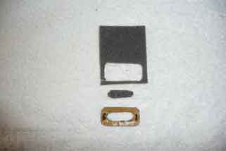 Figure 33 Figure 33
- Remove rocker switch holding plate from foam backing.
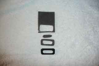 Figure 34 Figure 34
- Carefully separate the foam backing piece from the adhesive protection layer, and attached the foam adhesive piece to backside of the rocker switch holding plate.
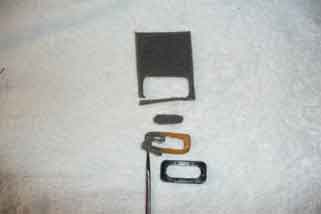 Figure 35 Figure 35
- Replace and snap into place rocker switch holding plate with rocker switch-wiring harness. Place switch holding plate over rocker switch-wiring harness and firmly snap into place.
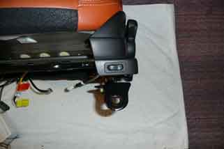 Figure 36 Figure 36
- Air bladder pump unit placement.
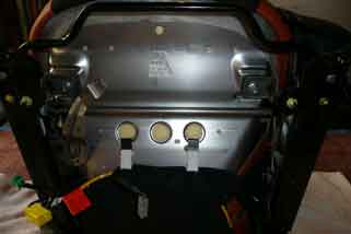 Figure 37 Figure 37
- Routing of plastic, self-locking cable ties to secure air bladder pump unit to underneath of driver's seat.
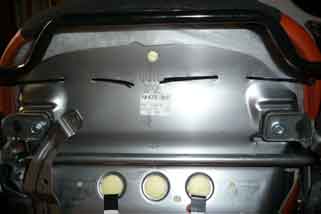 Figure 38 Figure 38
- Secure air bladder pump unit with 4-cable ties. Suggest placement as pictured for proper seat clearance during subsequent seat adjustments.
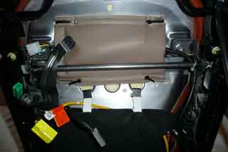 Figure 39 Figure 39
- Air bladder placement.
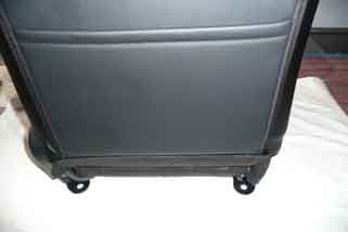 Figure 40 Figure 40
- Locate zipper at bottom of seat by firmly pulling down the leather-fabric locking panel.
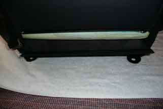 Figure 41 Figure 41
- Unzip and expose rear of seat. Drape seat-backing over front of seat.
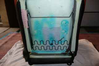 Figure 42 Figure 42
- Place supplied air bladder with bladder facing towards driver! Small height adjustments of air bladder, either up or down, maybe made. Set in seat, blow into air bladder filler tube, and adjust to desired fit.
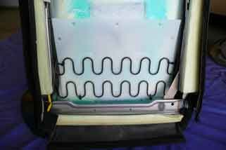 Figure 43 Figure 43
- Route air bladder filler hose to the left side of seat (as seated), and onto the air pump unit located under the front of the seat. Secure air bladder and filler hose with cable ties.
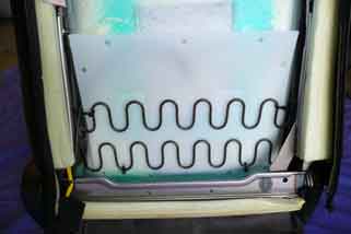 Figure 44 Figure 44
- Connect air filler hose to air pump unit. *NOTE - Make sure both the air pump unit electrical connector and the rocker switch electrical connector under the seat are freely accessible for their respective connections during seat reinstallation. Replace and zip close seat backing piece and resecure leather-fabric locking panel.
 Figure 45 Figure 45
- Reinstall driver’s seat and connect air pump unit connector and air pump rocker switch-wiring connectors. Reconnect ID’ed electrical plugs to white electrical junction box electrical and resecure the junction box onto the metal support arm! Resecure driver's seat, fuse box panel, and door sill panel by following reverse of removal steps.
 Figure 46 Figure 46
- View of reinstalled driver's seat with new air bladder pump unit rocker switch. Reinstall fuse box door, reconnect battery, seatbelt strap to strap guide, and test lumbar system. Installation complete for driver's seat.
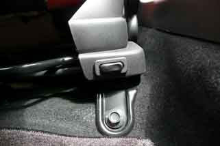 Figure 47 Figure 47
- Installation of passenger’s lumbar system is similar to driver’s seat. Disconnect battery, lower car top, remove door sill plate, and seatbelt strap from belt guide located on upper right of seat (as seated).
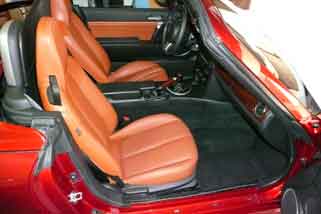 Figure 48 Figure 48
- Leave safety belt attached to lower seat area, remove 4 bolts securing seat to floorboard (see steps 6-7 ), and carefully remove seat to protected/padded work area “CLOSE TO CAR!” *NOTE – Seatbelt strap will stretch-out far enough to work on seat that can be located close to and outside of car.
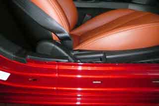 Figure 49 Figure 49
- Leave safety belt attached to seat and carefully remove seat. DO NOT twist seatbelt strap while removing or replacing this seat!
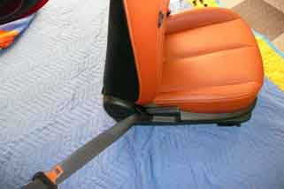 Figure 50 Figure 50
- Underside of passenger seat is a bit different than driver's side. Remove white electrical junction box, ID and remove electrical plugs. Follow steps 23 thru 36 to install rocker switch. Recommend locating rocker switch on right front of seat area (as seated) on hard plastic seat molding piece! *NOTE – The recommended mounting area for this rocker switch installation is smaller than on the driver’s seat.
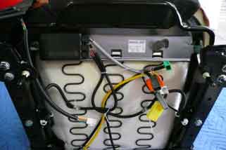 Figure 51 Figure 51
- Place white electrical junction box onto carpeted floorboard.
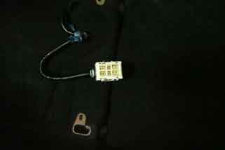 Figure 52 Figure 52
- Start of air pump unit installation.
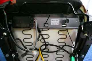 Figure 53 Figure 53
- Cont'd air pump unit installation. Use thin flathead screwdriver to assist threading cable ties thru openings.
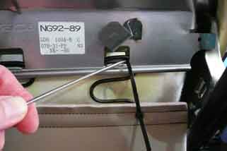 figure 54 figure 54
- Cont'd air pump install. Recommended placement of pump as pictured.
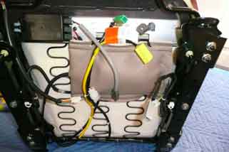 Figure 55 Figure 55
- Air bladder installation. Follow similar install steps 40 thru 44. *NOTE - Route air filler tube to right of passenger's seat (as seated) and onto air pump unit located under seat.
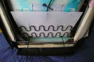 Figure 56 Figure 56
- Cont'd air bladder install.
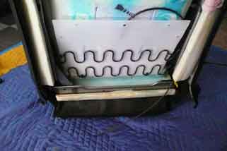 Figure 57 Figure 57
- Cont'd air bladder install.
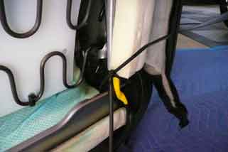 Figure 58 Figure 58
- Layout and size supplied lumbar air pump wiring harness that will connect to the air pump unit located under the front of the passenger's seat. DO THIS PRIOR TO CUTTING OR TRIMMING ANY OF THESE WIRES! Routing supplied wiring harness under carpet, no carpet cutting required. *NOTE - Supplied wiring harness is too short and will require adding additional wire lengths.
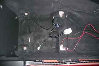 Figure 59 Figure 59
- Cont'd routing of wiring harness under carpet. Gently pull down carpet, and guide wires under carpet. Shown in picture wiring harness with added wire lengths. Retuck and flatten-out carpet back into place after install.
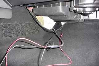 figure 60 figure 60
- Cont'd routing of wiring harness. Remove plastic dash cover from under steering wheel; thread supplied wiring harness thru back of the panel and onto interior fuse box panel. Choose best path/route to thread this wiring harness thru the back of the dash.
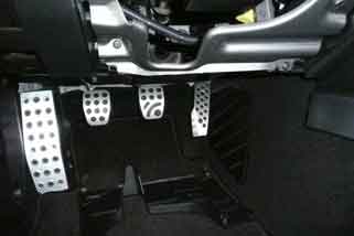 Figure 61 Figure 61
- Cont'd routing wiring harness. *NOTE - Addition of flexible plastic wire covering, and aiding in clean install.
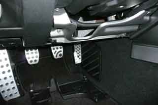 Figure 62 Figure 62
- Reopen fuse box panel (see steps 4 & 17 ). *Note - Ganging of 5-amp hot-leads, and grounds from driver's and passenger's lumbar electrical systems. This saves room within the fuse box area with no observed overloads or impacts on the car’s overall electrical system.
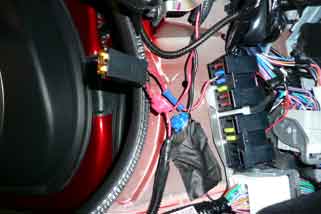 Figure 63 Figure 63
- Reinstall passenger’s seat and connect air pump unit connector and air pump rocker switch-wiring connectors. Reconnect ID’ed electrical plugs to white electrical junction box electrical and resecure the junction box onto the metal support arm! Resecure passenger's seat, fuse box panel door, and door sill panel by following reverse of removal steps. Reconnect battery, seatbelt strap to strap guide, and test lumbar system. Installation complete for passenger's seat.
*NOTE - Reinstalled 15-amp fuse in panel!
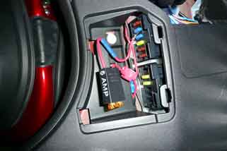 Figure 64 Figure 64
NOW PUT THE TOP DOWN & ENJOY A NICE LOOOONG
COMFOTABLE DRIVE IN YOUR NEWLY IMPROVED MX-5!
|